
iCircuit 3D gives you an endless virtual workbench upon which to design and test your electronics projects. It combines the robust electronics simulation engine of the original iCircuit with the latest rendering and 3D physics technology of iOS.
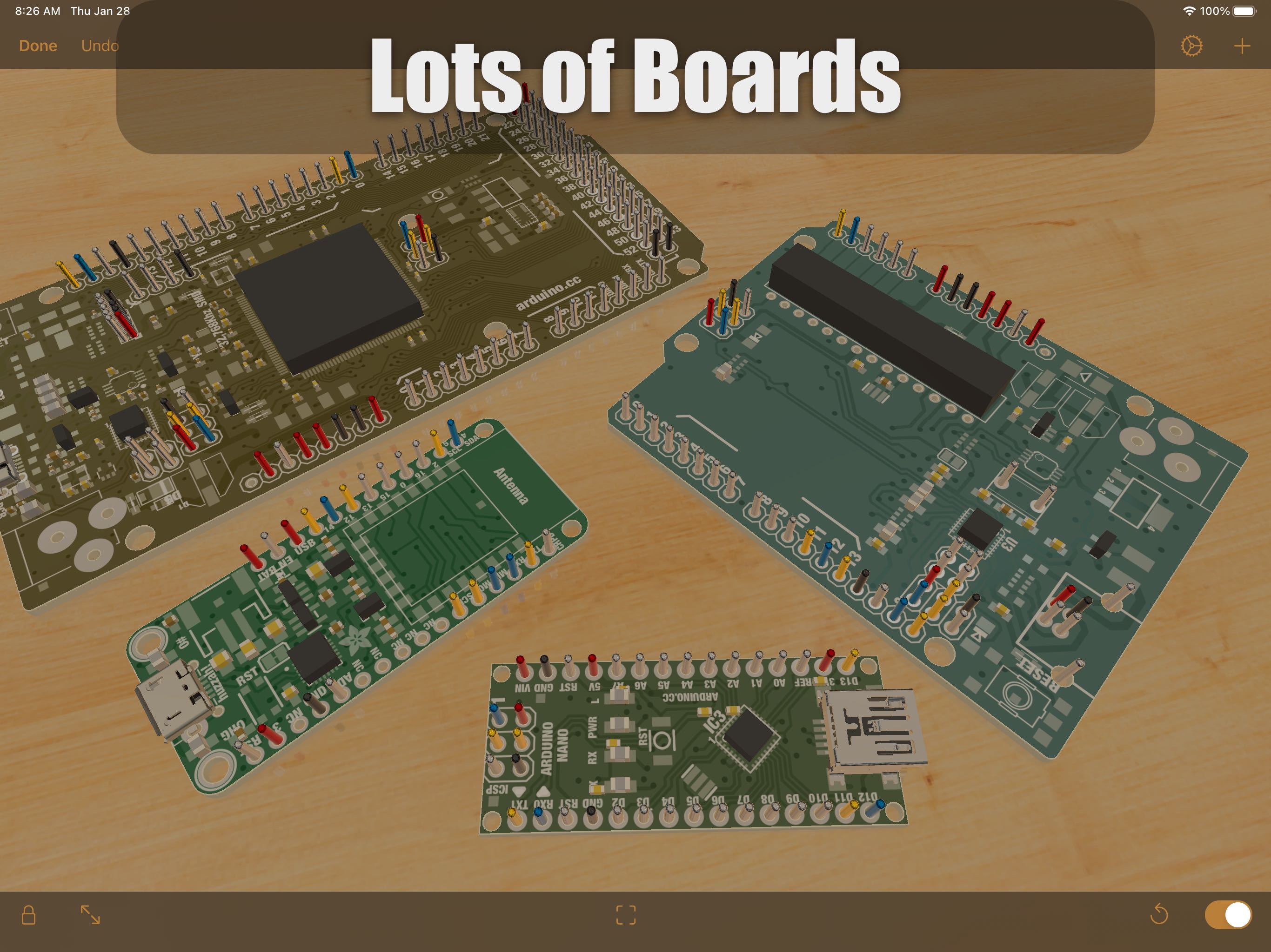
Don’t let the physical availability of parts be a constraint on your creativity! Choose from an expansive library of more than 150 physically and electronically simulated parts and over 1,000 reference boards to build and test your circuits for flaws, simulate your physical designs, and test your Arduino code in a fun sandbox environment. Each of these parts is adoringly rendered to look like the real thing so that you can enjoy the beauty of electronics.
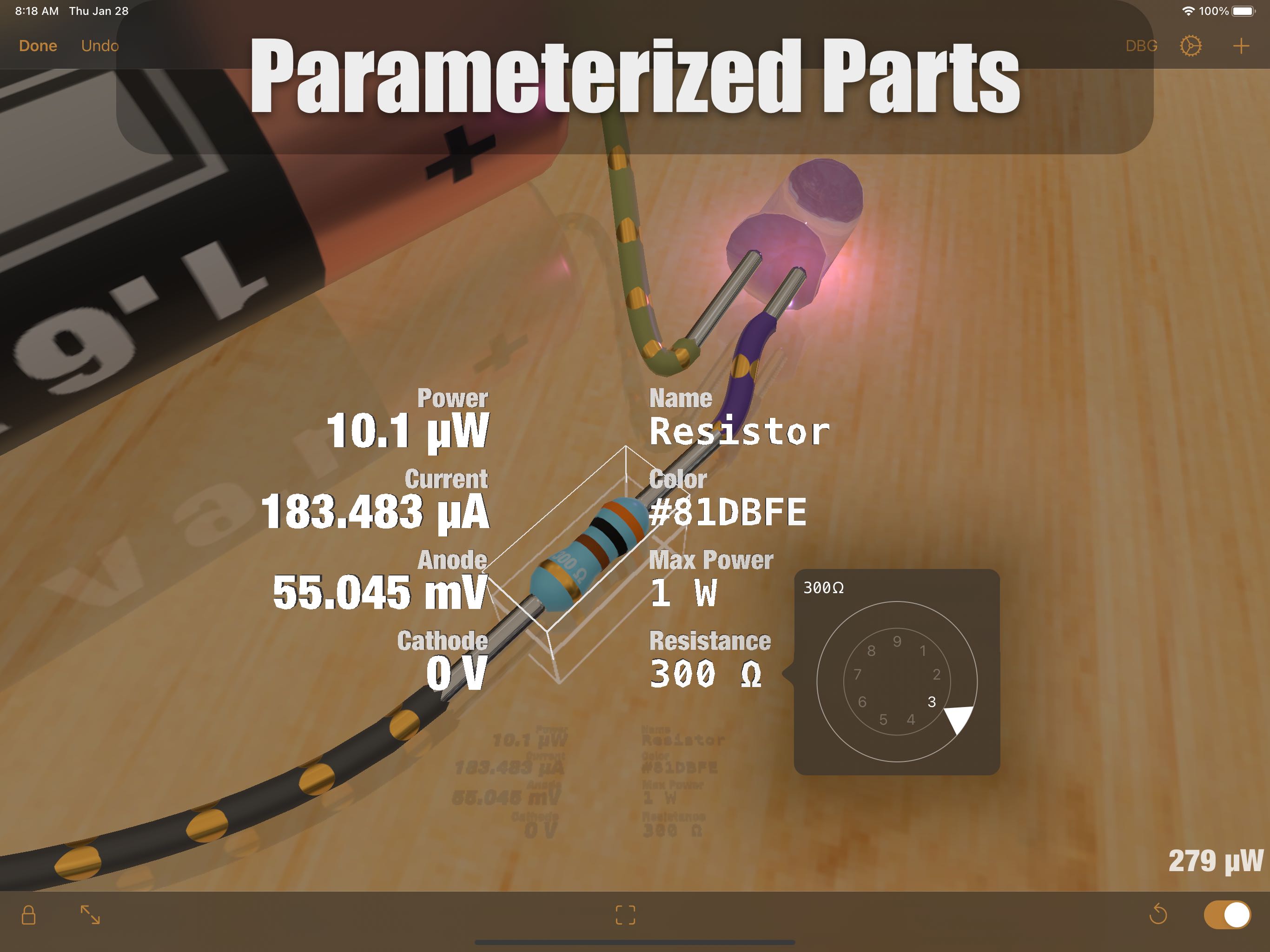
When powered, LEDs light up realistically, DC motors spin, and speakers make noise! Follow the flow of current along your simulated wires, and see pinout and color code data on the circuit components themselves. Tapping a part gives you quick access to simulated values such as voltage and current and also allows you to change the parameters of the part. In the event of a wiring issue or an over-stressed element, magic smoke will billow from the point of failure, making it easy to locate, diagnose, and fix errors. Add photographs and other reference images to the environment to keep them close at hand. You can even import your own 3D models to attach your electronics to, or use Blocks to build an enclosure, or a panel for them!
- Tons of resistors, capacitors, and LEDs
- Multiple breadboard and wiring elements
- Diodes, Transistors, and MOSFETs
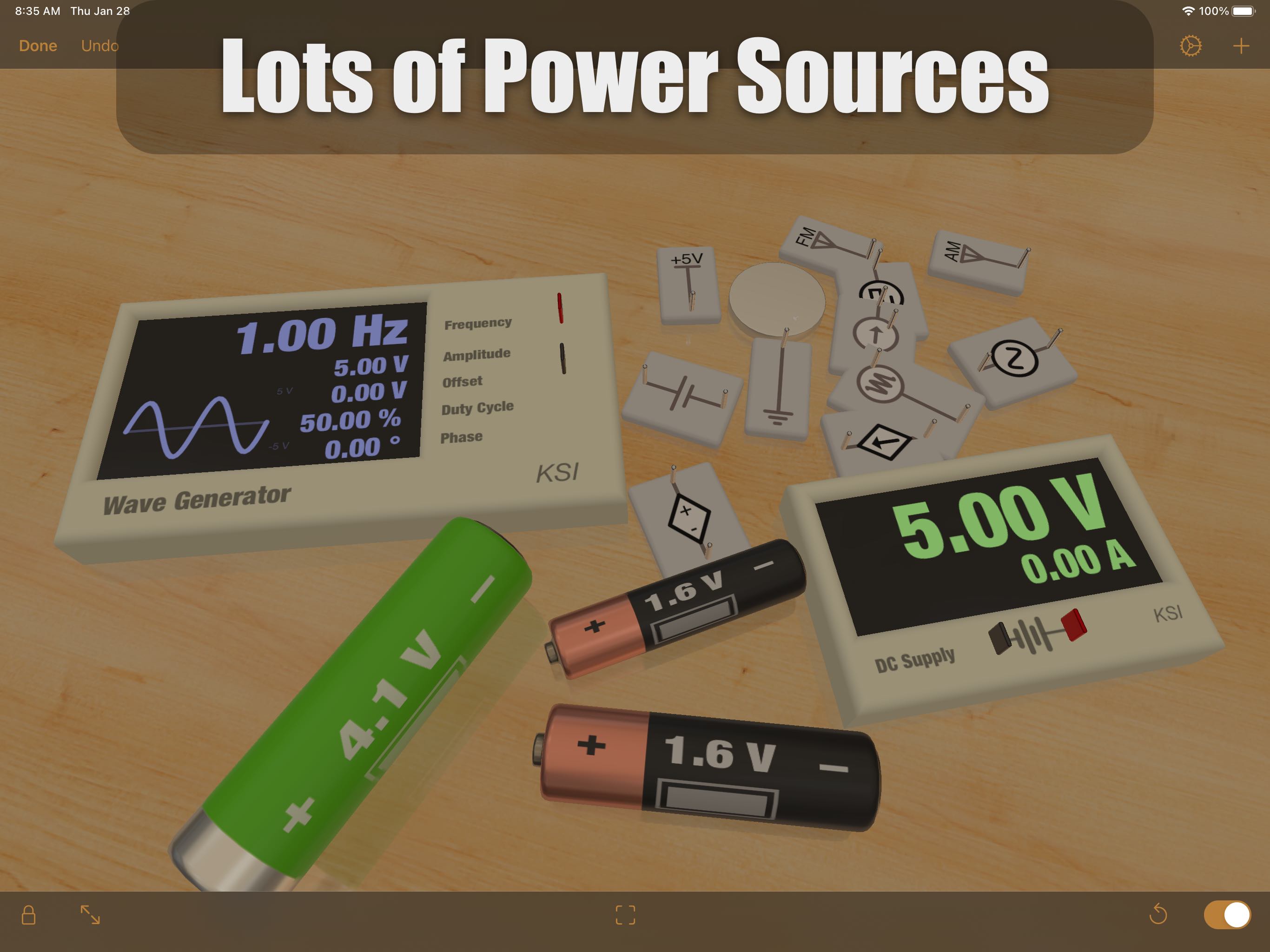
- DC power supplies
- Waveform Generators to make AC, Square, and Sawtooth signals
- Various batteries, including AA, AAA, 18650, and coin
- Switches, including SPST and SPDT
- Buzzers and speakers
- DC motors and Servos
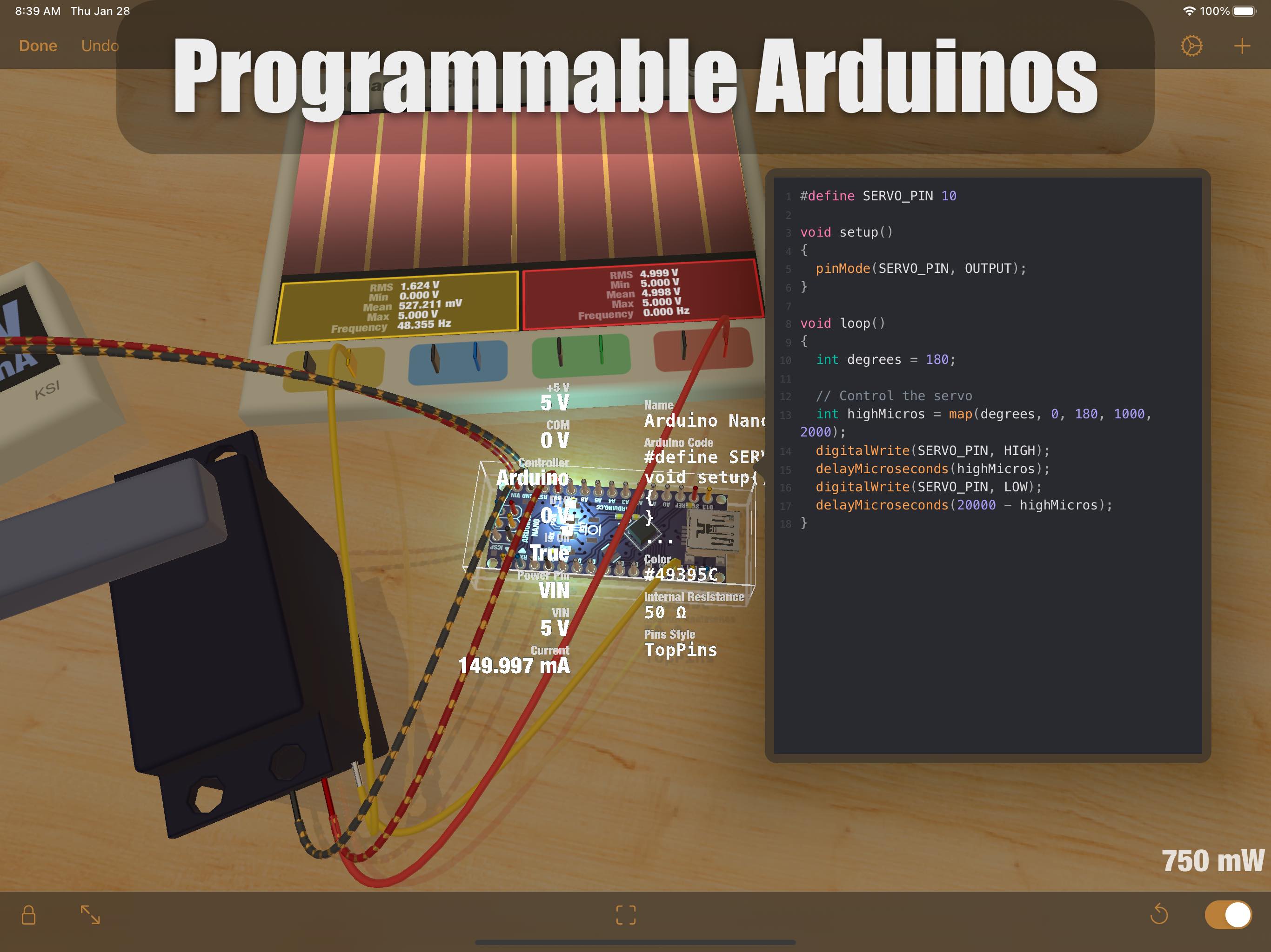
- Programmable Arduino elements!
- The full symbolic original iCircuit library
- Over 1,000 reference circuit boards. These are not fully simulated, but are great for layout out your designs.
- Import custom circuit elements in Eagle Board or Fritzing element formats (imported circuits won’t simulate, but you can at least wire them up)
- Import custom 3D models to attach your projects to, and simulate their behavior on the workbench
- Import images for reference or documentation, and they’ll appear as physical photographs
All of these are available in the 3D work environment that mimics an electronics workbench. When you add parts, they land on the table due to gravity. From there you can drag them around and connect them to each other by drawing wires between their ports. When a circuit is completed, they start simulating. Once connected to each other, wires stay connected no matter where the part is positioned. You can stick them to other parts to make panels and structures, or just leave them laying on the bench haphazardly, like I do.
iCircuit 3D was designed with a strong emphasis on fun and exploration and there are a lot more features along those lines to discover!
I hope you enjoy this new take on circuit software.
User Manual
This manual covers the basics of building circuits and explains how the simulation works.
Environment
iCircuit 3D shows an infinite wooden workbench upon which you can build your circuits. In this environment, there is gravity and the parts of the circuit can bounce off one another. You build circuits by adding parts and wiring them together through their ports. Once you have completed a circuit, you will see current traveling through those wires and voltages on those ports.
Moving Around
To move your position, drag the workspace.
Use two fingers to:
- Rotate around a point
- Pinch to zoom in and out
- Drag in the same direction to tilt
At any time you can tap the View All reticle in the bottom part of the screen to center your circuit on the screen.
Parts
Your circuit is made up of parts connected to one another using wires. All parts are physically simulated and most are electrically simulated.
Adding Parts
Open the library by pressing the + button. Then tap on a part to add it.
The part will fall from your position to land in the center of the screen. To add parts to a different location, move your view first. You can also reposition the part after it's been added.
The library item will switch to another variation of that part. It will have a different color and its parameters (such as the resistance of a resistor) will be randomized. It does this to keep a variety of parts in the library and to keep life interesting.
Importing Parts
If you have 3D geometry files, images, or even Eagle circuit boards, you can add them to your circuit by tapping an empty aread of the workspace and choosing the Import menu option.
Moving Parts
Move parts by dragging with your finger or the mouse. They do not need to be selected first. But if you have multiple parts selected, then they will all move. Parts will move along the work surface but will be raised if they collide with other parts.
If the part is stuck to another (such as a breadboard), the whole compound object will move.
If you wish to move an individual part that is stuck to another, then select that part first. Then the dragging operation will move just that part.
Rotating Parts
Place your finger on the object then use another finger to make a rotation gesture. The object will rotate in place. You can also perform this rotation gesture while you are dragging objects.
If you move both fingers in the same direction, the object will rotate on different axes.
If you have a keyboard, you can hold Command while dragging or scrolling to rotate the object.
Selecting Parts
Tap or click on a part to select it.
To select multiple parts:
- Select a part, then (while your finger is still on it)
- Use another finger to select an additional part or wire
If you have a keyboard, you can also hold Shift to select multiple objects by tapping or clicking them with the key held down.
Editing Parts
When you tap a part, it becomes selected and two sets of values will be displayed. On the left are measurements of its voltages, currents, and other interesting values of the part. On the right are its editable properties.
Tap a property on the right to edit its value. An editor will appear, usually a dial, that you can use to change the value.
Parts also have actions that can be executed. Tap the part a second time to see a menu of these actions. On Mac, right click the part to see the actions.
Edit Actions
The Delete action will delete all selected parts and any wires connecting them.
Cut, Copy, and Paste are also available to make building large circuits easier. Copy will place all the selected objects, and any wires between them, on the clipboard.
Duplicate is wonderful for making a bunch of identical parts (and towers). When you duplicate parts, they will be positioned just slightly above their original object.
Undo
All actions are undoable. When you hit Undo, your last edit will be undone and the simulation will be reset.
Wiring Parts
Most parts have ports that can be connected to one another to form circuits. Ports are usually distinguished by being shiny pointy-looking things.
To wire ports together, drag from one port to another. As you do this, the wire will show the port name of both devices to help you connect the right ports together.
If the circuit is complete and there is current going through the wire, then little "current dots" will animate on that wire showing the direction of the current.
You can rewire a port by dragging an end of the wire and moving it to another port. If you drag the end without making a connection, it will be automatically deleted.
You can manually delete a wire by selecting it, tapping again to reveal its actions menu, then tapping Delete. If you delete a part with wires attached, all those wires will be deleted.
Sticking Parts Together
Some parts such as Breadboards, Blocks, and other geometries allow other parts to be "stuck" to them. This allows you to build 3D structures, control panels, simple robots, and whatever else you can think of.
To stick a part to another, drag the part over the other part. The sticky part will capture it and perhaps re-orient it (blocks align themselves).
To move a stuck part, you must first select it. Once selected, you can drag it around.
To unstick a part, drag it off of the other sticky part.
Warning: iCircuit 3D technically allows infinitely large structures (as large as your device can simulate) but sometimes bites off more than it can chew. If it ever does something funny, try undoing your last operation or resetting the simulation.
Disassembling and Assembling
If you create complex structures using the sticking mechanism, it can be useful to disassemble those structures temporarily to check their connections. You can accomplish this by pressing the Assemble and Disassemble toggle arrows in the lower left part of the screen.
While disassembled, physical connections will be represented as wires and structures will collapse.
All parts are still editable while disassembled.
When reassembled, parts will combine into structures again.
Locking Parts
Circuits are editable by default, but you may want to lock the position and values of all the parts. Use the lock icon to do this. This makes it safe to show off your circuits to your friends or to prevent fat-fingering.
Simulation
There are two simulators in iCircuit 3D: an electronic circuit simulator and a physics simulator.
They can both be turned on and off using the toggle switch in the lower right.
They can both be reset to their initial conditions by pressing the reset arrow next to the toggle. This is especially useful if the physics simulation goes wild.
Electronics Simulation
The electronics simulator is a fixed time step simulator that calculates the voltages of parts' ports and the currents through those parts. Only parts with wires attached to them are simulated.
Board Simulation
The app comes with a library of over 1,000 custom boards from open source designs on the internet.
Unfortunately, these boards are not completely simulated. They can be added to your circuits but only their power pins will be simulated.
This same rule applies to any boards you import yourself from Eagle.
The Arduino Controllers are programmable and their ports are simulated. The programming language and editor implement a subset of the Wiring language and does not support external libraries. Notably C++ classes are not supported.
Magic Smoke
It is well known that electronic parts only work because they contain magic smoke. If you apply too much power to parts, you risk releasing that smoke and the part will no longer work.
If this happens, iCircuit 3D with dutifully report to you why the part is smoking.
(Real talk: electronic simulations often fail due to accidental short circuits. If your circuit starts smoking look for ports that you are trying to force to different voltages.)
Circuit Power and Batteries
The amount of power being consumed by the circuit is shown in the lower right of the screen.
If you have batteries in your design, then it will also display how much longer that circuit can keep running.
Batteries discharge in the app according to discharge curves based on their capacity. If a battery isn't giving you the expected voltage, then use its action menu to recharge it.
Physics Simulation
iCircuit contains a physics simulator to make part movement and interactions possible. You will notice the physics engine the most by the presence of gravity and the way parts bounce off each other.
I highly recommend building towers of parts and knocking them over.
The engine works like a robot simulator with rigid parts connected (or not) using joints. Joints come in two flavors: rigid joints and dynamic joints.
Rigid joints are created by "sticking" objects to one another. That compound object that acts as a single unit.
Flexible joints are created in the same way electrical wires are added: drag from one physical port (like the rotor of a motor) to another object.
Joints are visualized when you disassemble the circuit. From there they can be deleted or modified.
If you import a robot URDF, its joints will be added to the simulation.
Warning: The physics engine obeys Newtonian mechanics but is not a good representation of reality. Gravity is not as strong as it is in real-life and parts will sometimes freak out and spin off due to simulation errors. Reset the simulation if this happens - parts will return to their starting positions.
FAQ
The behavior of a simple LED circuit puzzles me: I would expect the difference between Anode and Cathode voltages to remain constant, and equal the forward voltage.
The forward voltage of a diode is only valid (more accurately, measured) at one particular current level. Diodes and all PN junction devices are current controlled with the voltage drop changing as necessary to accommodate the crystal structure’s maximum current transfer. The V drop should be approximately that spec number, but will only match the spec when the current matches the measuring conditions.
How are the Arduinos simulated?
The Arduino simulator simulates the execution of C code on a virtual machine. Most C functionality is implemented but only very few C++ features are implemented. Timing functions are only accurate to about 10ms because the virtual machine is run more slowly than a real device (about 500kHz vs 8MHz).
All of the Arduino functions are implemented. If you run into a problem with one, please let me know!
How do I debug Arduino code?
There is currently no debugger and the Serial functions are not visualized. Sorry. I'm working on both.
In the mean time, I use Scopes and digital pins to communicate events to know what's going on with my code.
When I scroll the library really fast, the app crashes!
Sorry, it’s running out of memory. It’s trying to load too much at once. I’m working on fixing this but suggest using the search box for now instead of scrolling very fast.